
Wall thickness is not just a geometric decision. In plastic injection moulding it affects how material flows, how it packs, how long it cools and how dimensionally stable the real part will be.
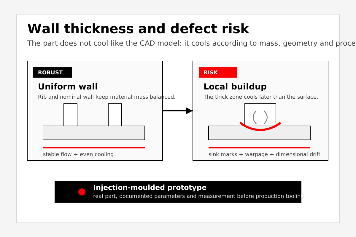
Plastic part design often refers to uniform walls, proportioned ribs and suitable radii. These are not cosmetic rules. They directly affect the injection moulding process.
When one area carries more material than the rest, it cools more slowly. The surface can solidify while the core is still shrinking. That mismatch later appears as sink marks, depressions, internal voids, warpage or loss of tolerance.
Key idea: CAD shows volume, but it does not confirm how that volume behaves when molten material fills the cavity, packs, cools and is ejected.
Why wall thickness matters more than it seems
Wall thickness defines strength, weight and stiffness, but it also defines process difficulty. A wall that is too thin can make filling difficult. A wall that is too thick increases cycle time, shrinkage and sink-mark risk. The goal is not to make everything thin, but to keep material mass coherent and mouldable.
Injection moulding design guides insist on uniformity because abrupt thickness transitions change flow and cooling rate. In real parts, that change can move functional dimensions or create internal stress.
Ribs: stiffness without turning the part into a block
Ribs add stiffness without increasing the whole nominal wall. But if a rib is too thick relative to its supporting wall, it stops being a lightweight solution and becomes a local material buildup.
The problem is not always obvious in the first visual prototype. It may appear as a slight mark on the opposite face, gloss variation, local bending after cooling or dimensional drift over time.
That is why an injection-moulded prototype lot is not only useful for checking whether the cavity fills. It checks whether ribs perform their function without penalising appearance, assembly or dimensional stability.
Bosses, screw towers and local joints
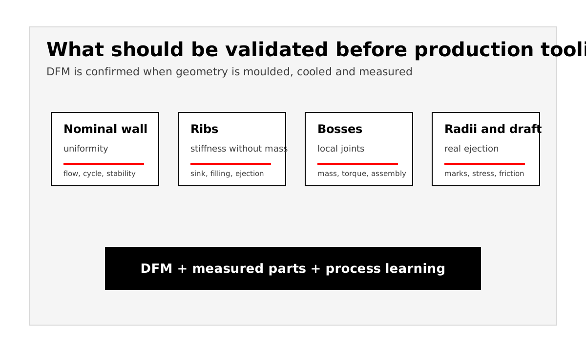
Screw bosses, housings, clips and joint areas concentrate material by definition. In CAD they may look like secondary details, but in the mould they behave as thermal hotspots and local shrinkage zones.
If a boss connects to an external wall without suitable relief, radii or supporting ribs, it can mark the visible face or deform the surrounding area. If it is relieved too much, it can lose strength or fail during assembly. Useful validation sits between those two extremes.
Why printed prototypes do not reveal this risk
A printed or machined prototype can help check volume, interference and assembly access. But it does not reproduce the differential shrinkage of an injection-moulded part or the thermal gradient between wall, rib and boss.
In 3D printing, the manufacturing logic is layered. In machining, the part is cut from stock. In injection moulding, material flows, packs, cools from the mould and shrinks according to geometry, material and process. Those mechanisms are different.
What to measure in an injection-moulded prototype lot
DFM review should become data. In a prototype moulding trial it is useful to check:
- Dimensions near ribs, bosses and wall-thickness transitions.
- Sink marks, gloss variation, flow marks or deformation.
- Flatness, warpage and stability after complete cooling.
- Assembly function: clips, screws, closures, pressure and repeatability.
- The relationship between observed defects and process parameters used.
When to change geometry and when to adjust process
Not every defect is corrected the same way. If a sink mark appears because packing is insufficient, the process may have margin. If it appears because there is disproportionate local mass, machine adjustment may hide the symptom but not remove the cause.
The value of an injection-moulded prototype is separating those cases. It supports decisions on whether to adjust parameters, modify an insert, thin a rib, relieve a boss or change a wall transition before investing in definitive tooling.
The practical question: before approving production tooling, do you know whether your ribs and bosses cool correctly, or only that they fit in CAD?
FAQ about wall thickness and DFM
Why is wall thickness critical in injection moulding?
Because it affects filling, packing, cooling, shrinkage and dimensional stability. A design with unbalanced material mass can fail even if it looks correct in CAD.
Can an oversized rib create sink marks?
Yes. If the rib concentrates too much material relative to the nominal wall, that area cools more slowly and may create a depression or visible mark on the opposite face.
Does DFM analysis replace an injection-moulded prototype?
No. DFM and simulation reduce risk before manufacturing. Testing injection-moulded parts adds physical evidence under the tested conditions without replacing final production-process validation.
What does pilot2plant add at this stage?
It produces parts with production material before production tooling so the team can check whether wall, rib, boss, radius and ejection decisions work under real process conditions.
Cross-checked official technical sources
- ISO 20457:2018 - Tolerances and acceptance conditions for plastics moulded parts
- BASF - Ultramid injection-moulding processing guidance
- Celanese - Fortron PPS design manual
These sources support the general principles. Applicable acceptance criteria must be defined for the material grade, design, process, sector and agreed requirements.