Tolerance stack-up explains why an assembly can fail even when every individual part is within drawing limits. In plastic parts, that risk is only truly understood when the assembly is measured with injection-moulded parts in the production material.
On an individual plastic part, the dimensional report can look clean: dimensions within specification, acceptable deviations and no obvious warning signs. But when that part is assembled with three others, the final function may still fail.
The issue is not always a single part out of tolerance. Often, it is the sum of small accepted variations, one component at a time. That is tolerance stack-up.
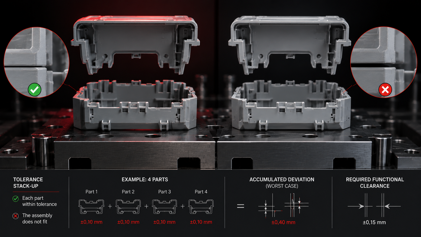
Key idea: a +/-0.10 mm tolerance may look small on an individual part. In a functional chain of four components, it can become +/-0.40 mm in a worst-case analysis, which assumes that all deviations point in the most unfavourable direction at the same time. When the relationship is approximately linear and the contributions are independent, RSS (Root Sum of Squares) can be used, which calculates stack-up as the square root of the sum of the squared tolerances: in the same example, the result would be +/-0.20 mm. Worst case is more conservative and is used when the risk leaves no room for failure; RSS is a statistical model whose validity depends on its assumptions being met and documented. In both cases, if the functional clearance of the assembly is smaller than the calculated stack-up, the assembly may fail even when every part has passed inspection.
What tolerance stack-up means in a plastic assembly
A part tolerance defines the acceptable dimensional variation for that part in isolation. In an assembled product, however, function depends on a chain of dimensions: clips, housings, closures, guides, seals, shafts, tabs or support areas.
When several parts contribute to the same function, their deviations do not disappear at assembly. They add up. Sometimes they compensate each other; sometimes they align in the worst possible direction.
Why approved parts can create a non-conforming assembly
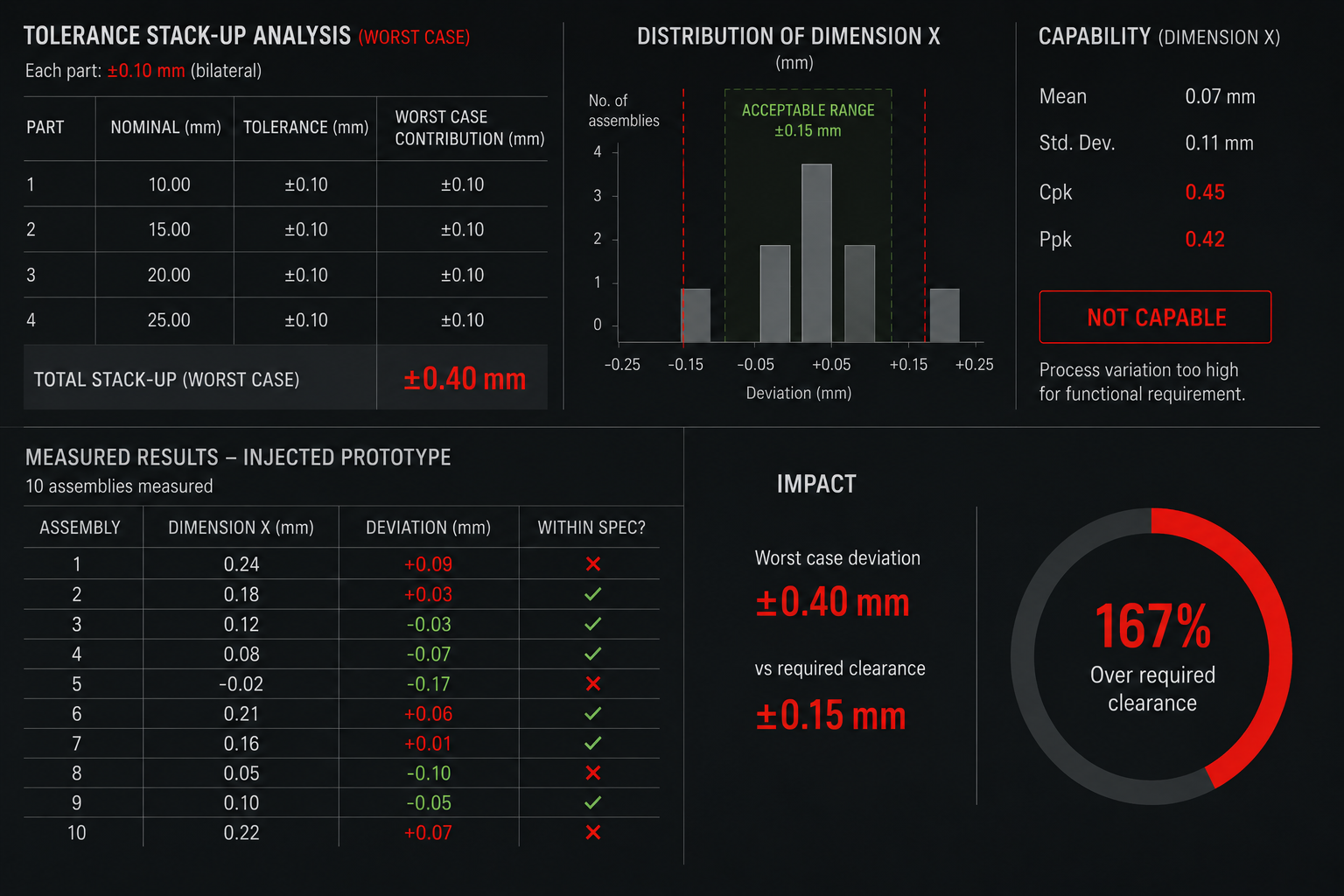
Consider an assembly made of four plastic parts. Each has a bilateral tolerance of +/-0.10 mm in one critical direction. If all deviations point in the same direction, the assembly can accumulate up to +/-0.40 mm.
That worst-case scenario does not mean all parts are wrong. It means the assembly design does not have enough margin to absorb normal process variation.
In injection-moulded plastics, this risk increases because final dimensions do not depend only on CAD. They also depend on shrinkage, fibre orientation, warpage, mould temperature, packing, gate location and local geometry.
Why 3D-printed or CNC prototypes do not reveal the real tolerance chain
A 3D-printed or CNC-machined prototype can be useful for ergonomics, volume checks, basic interference checks and assembly concept review. But it does not reproduce the dimensional variability of a part injection-moulded in the production material.
- FDM: introduces layer anisotropy and process-specific thermal deformation.
- SLA or SLS: can provide good geometric precision, but it does not reproduce thermoplastic shrinkage in production material.
- CNC: validates a machined geometry, not a part made by filling, packing and cooling inside a mould.
This is why an assembly may work with printed or machined parts and then fail with injection-moulded parts. It is not only the manufacturing route that changed; the real distribution of variability changed with it.
The role of production material in dimensional variability
Material shrinkage is not a single number applied uniformly across the whole part. It changes with wall thickness, flow orientation, fibre content, cooling conditions and geometric constraints.
In fibre-filled materials, for example, shrinkage can differ in the flow and transverse directions. In parts with uneven walls, deformation may concentrate exactly where the assembly function is most sensitive.
A tolerance stack-up analysis based on real data needs real parts: injection-moulded, in the production material and under a documented process window.
When to validate tolerance stack-up
There are two possible moments to discover a tolerance stack-up issue. The first is the injection-moulded prototype batch, when there is still room to adjust design, modify inserts, review tolerances or change the assembly strategy.
The second is production start-up, with the production mould already built, launch timing committed and every correction multiplied in cost.
The difference is not theoretical. In the first case, the team corrects with engineering evidence. In the second, it corrects under industrial pressure.
What to measure in the injection-moulded prototype batch
To make the analysis useful, it is not enough to assemble a few parts and check whether they close. Document at least:
- Functional dimensions involved in the tolerance chain.
- Nominal-versus-actual measurements on a sufficient sample of each component.
- Deviation direction and dispersion for each critical dimension.
- Process conditions used to manufacture the batch.
- Functional assembly result: clearance, interference, closing force, sealing or play.
The practical question: would you rather find the tolerance chain in the prototype batch, with room to correct, or at production start-up, with the mould already paid for?
Frequently asked questions about tolerance stack-up
What is a tolerance stack-up analysis?
It calculates how dimensional variations from several parts accumulate within the same assembly function. It shows whether the final product keeps enough functional margin when each component varies within its own tolerance limits.
Can it be done only with CAD data?
CAD allows a theoretical worst-case analysis. Real validation requires measurements from parts manufactured with the intended process and material, because shrinkage, warpage and real dispersion do not appear in the nominal model.
How many parts are needed to validate tolerance stack-up?
It depends on the objective, risk, expected variability and analysis method. An exploratory review can find obvious issues with a limited sample, but its size must be justified and cannot by itself demonstrate capability. Estimating Cpk also requires a stable process, sufficiently independent data, a suitable distribution and a statistically defensible sample. Results should be linked to the documented process conditions used for the batch.
What does Pilot2Plant contribute to this type of validation?
It enables an injection-moulded prototype batch in real production material before the production mould. That batch provides dimensional data, process behaviour and assembly samples to decide whether the design has enough margin before investing in final tooling.
Cross-checked official technical sources
- ISO 20457:2018 - Tolerances and acceptance conditions for plastics moulded parts
- NIST IR 6223 - Design for tolerance of electromechanical assemblies
- NASA TP-2000-207428 - Tolerance analysis methods and RSS assumptions
These sources support the general principles. Applicable acceptance criteria must be defined for the material grade, design, process, sector and agreed requirements.