
An insert can fit in CAD and still move during injection. Learn which tolerances, datums and tests a prototype should validate before production tooling.
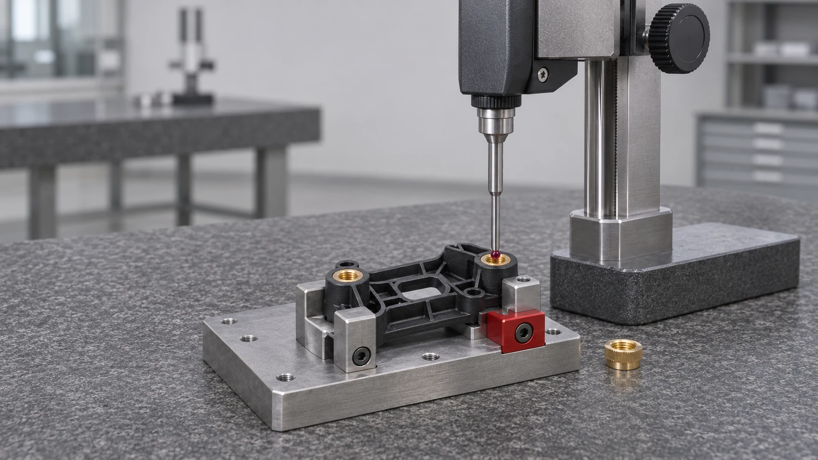
An overmoulded insert is not validated when it fits into its pocket. It is validated when it keeps its position and function while molten plastic fills the cavity, packs the part and completes cooling. That distinction prevents a common mistake: approving the CAD assembly and discovering later that the insert rotates, shifts, flashes or loses the intended retention.
The metal to polymer interface combines two tolerance systems. The insert brings dimensions, surface condition, mass and locating features. The moulded part brings shrinkage, pressure, flow, temperature and geometry that can change during the cycle. A prototype should test their interaction under representative conditions, rather than checking each nominal dimension in isolation.
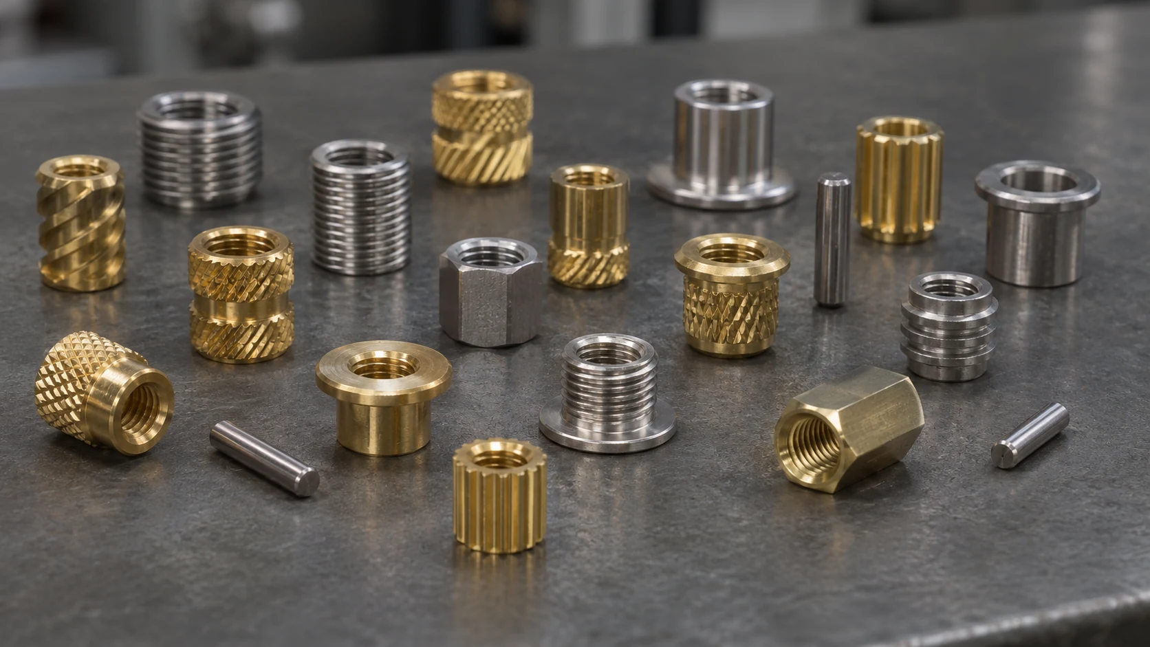
Before moulding, the product definition must identify the functional datums. The team should then agree which displacement, rotation or insertion depth makes the final function unacceptable. It should also record the incoming insert condition, including features that could affect seating or bonding.
CAD does not reproduce every risk. Melt pressure can push an insert against a locating wall or lift it if retention does not counter the flow force. Material can enter an interface and create flash. Different heat dissipation can change local filling, shrinkage and appearance. The first trial therefore needs more than an insert-presence check. It needs position measurements against agreed datums, interface inspection and a functional retention test that reflects the real use case.
A useful prototype protocol has four stages: inspect the incoming insert and loading device, measure position after moulding and conditioning, test the relevant functional load, and compare several parts while recording process settings. ISO 20457 places part tolerances in the context of material, design, tooling and processing. ISO 294-1 supports reproducible reporting of moulding conditions. ISO 294-4 helps distinguish shrinkage effects from an assumed insert-position error.
The industrial decision is ready when the team can state what locates the insert, what variation remains functional, which process conditions preserve that position and what evidence proves the interface works. If every part still needs manual adjustment, a design or process uncertainty remains before production tooling.