
Weld lines appear where flow fronts meet. They may be cosmetic only, or they may compromise strength, sealing and functional validation.
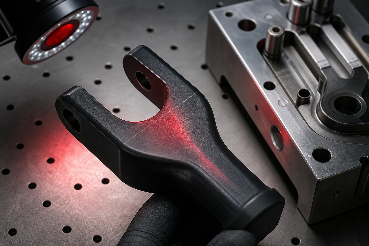
Where weld lines start
A weld line appears when two fronts of molten material meet during filling. It often happens around holes, inserts, section changes or when several gates are used.
They are not always critical defects
In some parts the weld line is only an acceptable visual mark. In others it falls on a load area, clip, hinge, seal or visible surface. Then it stops being cosmetic and becomes functional risk.
Why the prototype matters
CAD shows geometry and simulation can anticipate likely position. But actual strength and appearance depend on flow-front temperature, pressure, venting, material, fibre loading and process conditions.
What can be changed
Gate position, local wall thickness, venting, mould temperature and filling speed can move or improve the weld line. Some corrections are simple in prototype and expensive in production steel.
Validate where it hurts
The key question is not whether a weld line exists, but where it falls and what that area must do. If it is in a critical zone, the prototype must measure strength, sealing or appearance before final tooling approval.
Turning a weld line into a verifiable criterion
The review should define the location, affected function and failure mode to avoid. On a flexible tab this can be break load; beside a seal, leakage; on a visible surface, contrast or finish continuity. Acceptance should not rest on a photograph alone: it needs a limit, test method and defined part condition before the sample is moulded.
Reading the flow before changing the mould
A gate-location change can move the line to a less loaded area, but it also changes pressure, fibre orientation and filling time. Raising temperature or speed can improve flow-front joining, while reducing the margin against flash, degradation or trapped air. Each adjustment should therefore be compared with a baseline condition using the same functional criterion.
Prototype validation plan
Keep parts from both the baseline and corrected condition, identifying material, cavity, relevant parameters and line location. Visual inspection locates the line; functional testing decides whether it is acceptable. If the result remains process-sensitive, the industrial decision can be to redesign the geometry, move the gate location or reserve additional validation before final production steel is committed.
Technical sources
Frequently asked questions about weld lines
What is a weld line?
It is the mark or weak area that appears when two fronts of molten material meet during cavity filling.
Is it always a serious defect?
No. It may be cosmetic in a non-critical area, but it can compromise strength, sealing or appearance if it falls in a functional zone.
What can be changed to improve it?
Gate position, local wall thickness, venting, mould temperature or filling speed can be adjusted depending on the real cause.