
A shrinkage value in a material data sheet is a necessary reference, not an exact prediction for every part. Turning it into a tooling decision requires a clear definition of what is measured, when it is measured and which conditions must remain representative.
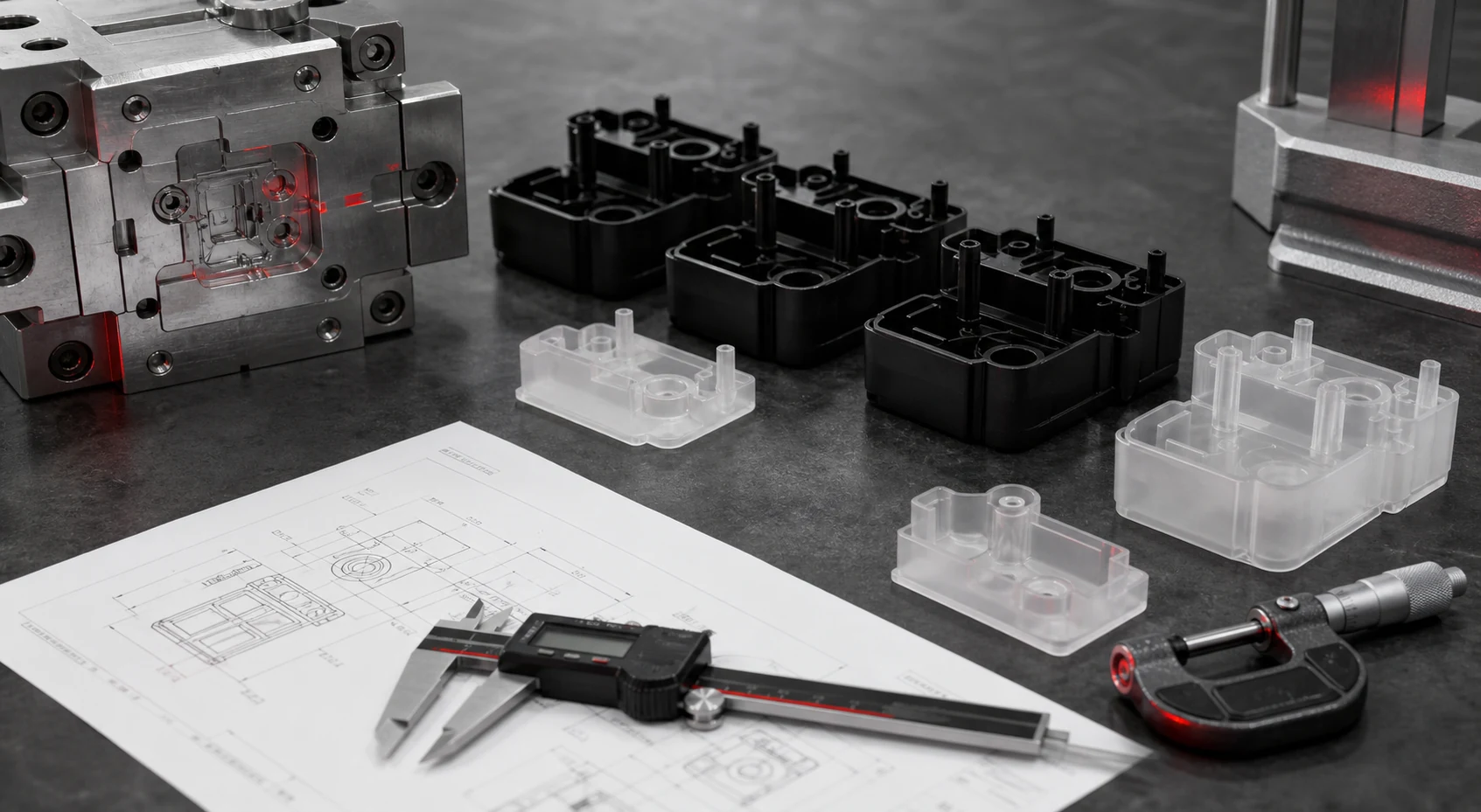
Key point: moulding shrinkage and deviation from the drawing are related, but they are not equivalent. Confusing them can lead to an incorrect tooling adjustment.
What moulding shrinkage actually measures
Moulding shrinkage compares a part dimension with the corresponding mould-cavity dimension. Measurement direction, timing and conditioning must be defined. In simplified form:
Comparing only the part with its drawing answers a different question: whether the part meets its dimensional requirement. That deviation may also include tooling tolerances, warpage, measurement uncertainty and dimensional change after demoulding.
Why material data are a reference
Published values come from methods and conditions stated by the material manufacturer. They support initial cavity sizing and material comparison, but the final component introduces its own geometry, wall sections, flow path and constraints. Treat the stated range as a design hypothesis and verify critical dimensions using a representative part.
Variables that change the result
Shrinkage can vary with material and batch, wall thickness, geometry, gate size and position, melt and mould temperatures, packing pressure and time, and cooling. In reinforced materials, fibre orientation can produce different shrinkage parallel and transverse to flow.
Time also matters. ISO 294-4 distinguishes moulding shrinkage from post-moulding shrinkage. Some materials continue changing after demoulding because of relaxation, temperature or moisture uptake. A report must state conditioning time and conditions; otherwise, two valid measurements may not be comparable.
What an injection-moulded prototype contributes
A prototype batch allows critical-to-quality characteristics (CTQs) to be measured, trend and spread to be separated, each result to be linked to recorded parameters, and assembly or function to be checked. When actual cavity dimensions are available, shrinkage can be calculated in selected directions instead of recording only deviation from the drawing.
The evidence can justify changes to cavity or insert dimensions, part geometry, gate position or the process window before production tooling is built. Each change should address a verified cause, not a single isolated dimension.
Limits when transferring the result
A prototype reduces uncertainty, but it cannot guarantee identical transfer if material, feed system, cooling, cavity count, machine or cycle change. The more representative these elements are, the more useful the forecast becomes. Production tooling and its process must still be validated under their own conditions.
Measurement checklist
- Define the dimensions, directions and equipment to be used.
- Record the actual cavity dimensions required for the shrinkage calculation.
- Set conditioning time and conditions before measurement.
- Separate parts by cavity, process condition and production order.
- Record material, batch, temperatures, packing, cooling and cycle.
- Measure CTQs and retain identified reference samples.
- Report shrinkage, warpage and dimensional deviation separately.
Frequently asked questions
Is deviation from the drawing the same as moulding shrinkage?
No. Shrinkage is calculated against the corresponding cavity dimension. Deviation from the drawing may also include tooling tolerances, warpage, conditioning and measurement uncertainty.
Why does the material shrinkage value not exactly match the actual part?
Because it is a reference obtained under stated conditions. The actual component is affected by geometry, wall thickness, gate position, packing, temperatures, material orientation and conditioning.
Does measuring a prototype guarantee production-tool shrinkage?
Not automatically. Transfer is stronger when material, geometry, gating, cooling, machine and process window are representative.
Technical sources consulted
- ISO 294-4:2018: determination of moulding and post-moulding shrinkage
- ISO 20457:2018: tolerances and acceptance conditions for moulded parts
- BASF: Ultramid processing recommendations
- Celanese: Celcon POM processing guide
These sources support the method and general variables. The value applicable to a specific part must be established using the data for its material grade and representative measurements.