
Delayed warpage is risky because it creates a false sense of security: the part looks correct, the first check seems acceptable and the problem appears later, when the plastic part is resting, being transported, assembled or functionally tested.
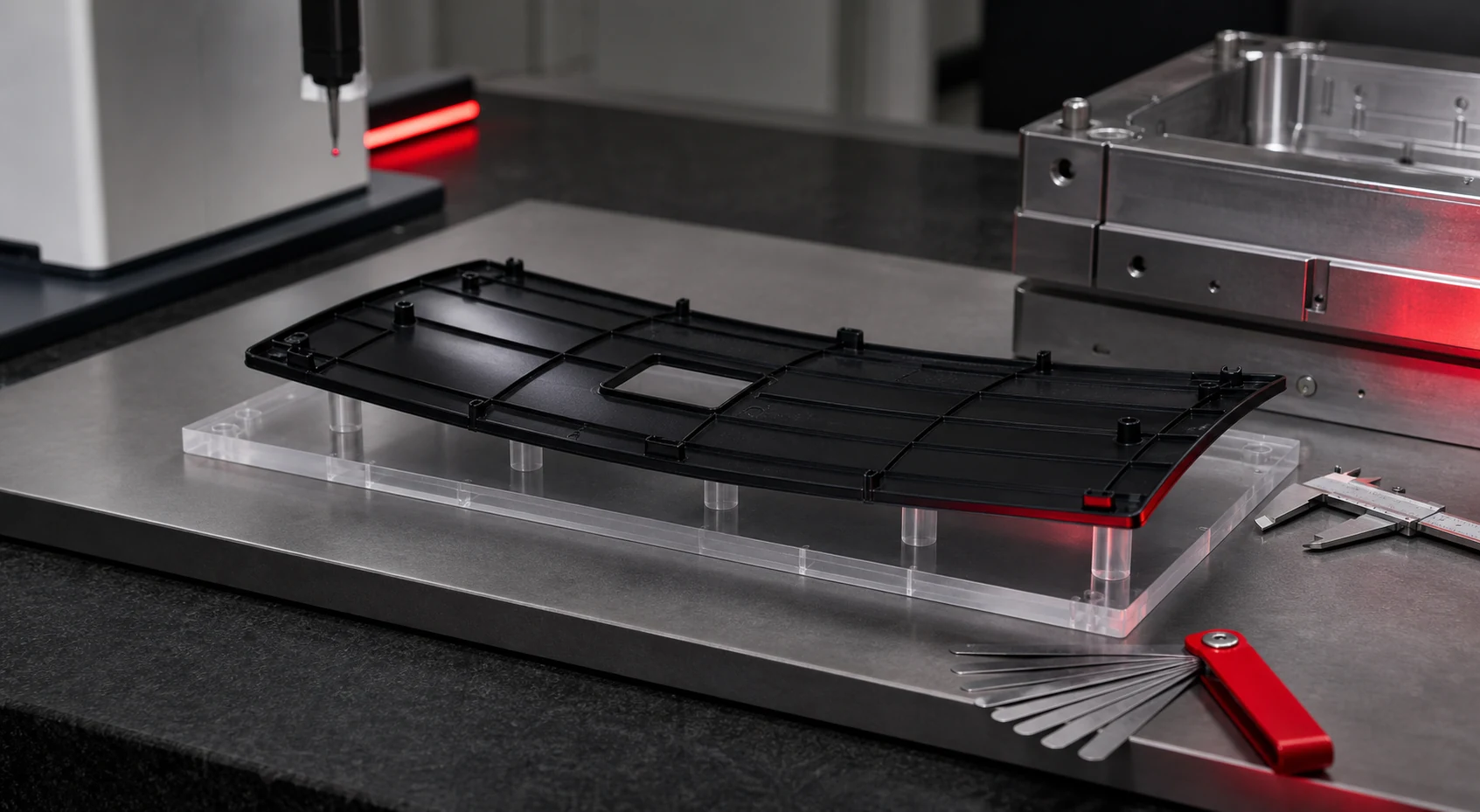
Key idea: validating an injection-moulded part is not only checking whether it fills. It also means proving that shape, functional planes and critical dimensions remain stable after the part has settled.
The issue is not just that the part bends
A small deformation may look harmless on an isolated component, yet it can be critical in the assembly. It can open a seal, move a clip, change closing force, shift a datum support or create a visible gap in an appearance area.
That is why delayed warpage should be evaluated through function: flatness, parallelism, fixing-point position, closure against another part, sealing, gauge checks, clip behaviour or assembly repeatability. If acceptance only checks a nominal dimension, the real risk may remain hidden.
What changes after demoulding
After ejection, the part is not necessarily at equilibrium. The material core can remain warmer than the surface, different areas can shrink at different rates and internal stresses generated during filling, packing and cooling can relax over time.
In semi-crystalline materials, post-moulding shrinkage can matter because the material structure continues to stabilise. In polyamides, moisture can also change dimensions and properties, so a single dry measurement is not enough if the part will work under different ambient conditions.
Fibre orientation in reinforced materials adds another factor: shrinkage can differ in the flow direction and across the flow. When the geometry combines long walls, ribs, thickness transitions and asymmetric flow paths, that anisotropy can become warpage.
Geometries where it tends to appear
- Long or flat parts with demanding flatness requirements.
- Covers, housings and frames that must close against another component.
- Ribs concentrated on one side or with disproportionate heights.
- Abrupt wall transitions, thick masses and local material accumulations near the gate.
- Lugs, clips or bosses that pull a thin wall during shrinkage.
- Fibre-reinforced materials, especially when the flow direction does not support the dimensional function.
How to measure it so the data are useful
Useful measurement starts before the sample is produced: the team must define what will be considered stable, which fixture will be used and under which conditions. Measuring a flexible part without repeatable support can confuse real deformation with measurement variation.
Minimum recommended protocol
- Define critical dimensions, datum planes and the functional acceptance criterion.
- Measure the first sample at ejection only as a reference, not as final approval.
- Repeat measurement after a few hours and at least after 24 hours; extend to 48 or 72 hours when material or function requires it.
- Record ambient temperature, humidity, resting orientation and any fixture applied to the part.
- Use the same fixture, support and measurement sequence every time.
- Keep retained samples to compare dimensional evolution and real assembly behaviour.
Variables worth separating
If warpage appears, the cause should not automatically be assigned to design. It can combine material, geometry, process and measurement method. Separating variables avoids changing the wrong thing.
| Variable | What to review | Why it matters |
|---|---|---|
| Material | Family, grade, reinforcement, moisture and post-moulding shrinkage. | Dimensional stability depends on real polymer behaviour, not only on CAD. |
| Geometry | Wall thickness, ribs, local masses, symmetry and functional supports. | Thickness and stiffness imbalance can turn shrinkage into deformation. |
| Process | Mould temperature, melt temperature, packing pressure and time, cooling and ejection. | The same design can behave differently when the process window changes. |
| Measurement | Datum, fixture, measurement time, environment and acceptance criterion. | Without a repeatable method it is impossible to know whether the part is drifting or the inspection adds variation. |
What Pilot2Plant learns before production tooling
An industrialisable prototype mould makes it possible to injection-mould real parts and observe whether the problem appears with representative material, gate, packing and cooling. That evidence arrives before steel, peripherals and final production-tool geometry are locked.
| Observed result | Technical reading | Possible decision |
|---|---|---|
| The part is stable at ejection and after 24 hours. | The dimensional risk is bounded for that material and process condition. | Move forward with documented acceptance criteria. |
| It looks right but drifts later. | Post-moulding shrinkage, stress relaxation or conditioning is relevant. | Adjust measurement, process, geometry or material before production tooling. |
| Warpage changes with flow direction. | There may be anisotropy from fibre orientation or unbalanced filling. | Review gate location, wall thickness, ribs and filling strategy. |
| The individual dimension passes but assembly fails. | The real criterion is functional, not only dimensional. | Make assembly or functional testing a critical-to-quality characteristic. |
Common mistakes
- Approving the part only from immediate post-ejection measurement.
- Using one good sample as proof of stability.
- Measuring without a repeatable fixture or datum plane.
- Changing material between prototype and production and assuming warpage will remain the same.
- Ignoring moisture and conditioning in polyamides.
- Not connecting deformation to the final assembly or function.
Frequently asked questions about delayed warpage
How long should an injection-moulded part rest before measurement?
There is no universal time. A practical screening sequence is measurement at ejection, after a few hours and at least after 24 hours. Materials sensitive to moisture, temperature or crystallisation may require longer follow-up with ambient conditions documented.
Are delayed warpage and shrinkage the same thing?
No. Shrinkage changes dimensions; warpage changes shape, flatness or relative position between areas. They can share causes: uneven cooling, fibre orientation, insufficient packing or wall-thickness imbalance.
Does simulation replace an injection-moulded prototype part?
It should not replace it when the decision depends on assembly, flatness or real dimensional stability. Simulation helps anticipate risk; an injection-moulded prototype confirms behaviour with representative material, gate, packing, cooling and ejection.
Technical sources checked
- ISO 294-4:2018: method for determining moulding shrinkage and post-moulding shrinkage in injection-moulded thermoplastic test specimens.
- ISO 20457:2018: tolerances and acceptance conditions for plastic moulded parts.
- BASF Ultramid: polyamide family with dimensional stability, reinforcement options and grade-specific processing requirements.
- Celanese Celcon POM processing guide: processing guide connecting warpage with thermal uniformity, ejection, pressure, temperature, mould-close time and wall-thickness variation.
The sources above support the general mechanisms of shrinkage, dimensional stability, tolerances and process variables. The final decision for a specific part still requires testing with representative material grade, geometry, gate and processing conditions.