
Jetting can leave serpentine marks and concentrate appearance or functional risk. A prototype detects it with real material and process conditions before production tooling is committed.
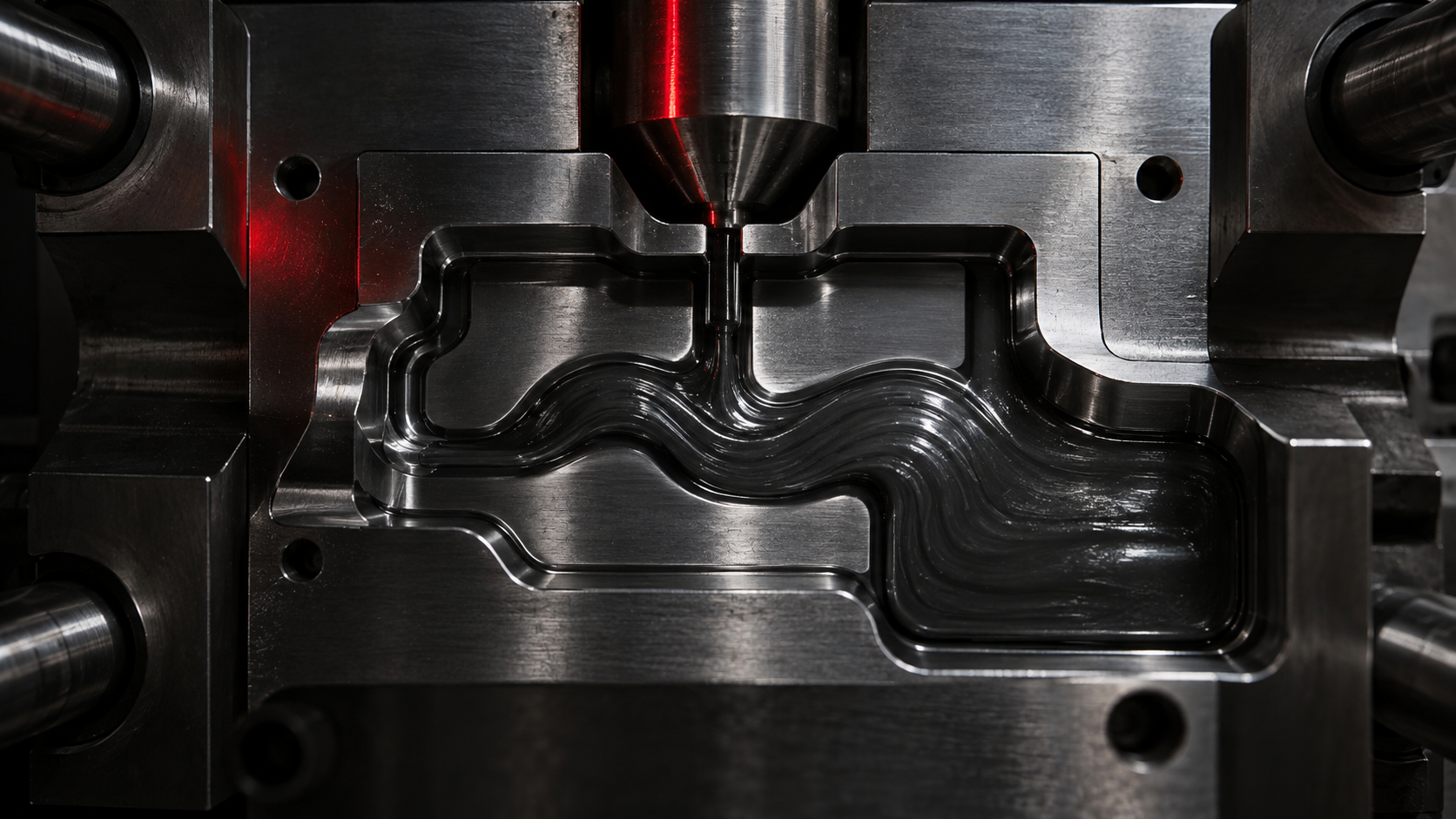
Key idea: jetting is not solved only by raising or lowering speed. The prototype must validate how injection point, geometry and process window interact in the real part.
What jetting is and why it matters
During filling, molten material should advance as a front that progressively contacts the cavity walls. Jetting happens when it enters as a free jet, travels through part of the cavity without stabilising and then folds on itself. On the finished part it may appear as a wavy or serpentine mark, especially under raking light.
Severity depends on where it lands. On a non-visible face it may be an acceptable cosmetic condition; on a sealing surface, loaded area, clip or appearance-critical part it can become an acceptance risk. The useful question is therefore not only whether jetting exists, but what the affected zone must do.
Conditions that encourage it
Jetting often appears when incoming material does not quickly meet a wall, core or feature that distributes flow. An injection point that is too small for the required flow, an unfavourable orientation or excessive initial speed can increase the risk. Melt temperature, mould temperature and the viscosity of the actual grade also change the response.
Geometry matters as much as machine settings. The same part may respond differently if the injection point moves slightly, its section changes or the flow is directed against a surface that opens it. Compensating only with process parameters can hide an unresolved design decision.
Why simulation does not replace the part
Simulation helps anticipate flow paths, pressures and meeting areas. However, local jet behaviour depends on real material condition, effective temperature at the start of filling and cavity details that should be contrasted with a physical part. Simulation guides the hypothesis; the prototype turns it into evidence.
A useful trial is not one apparently correct part. It compares reasonable speed, temperature and packing conditions, observes the mark under controlled light and checks whether the area retains dimensions, finish and function after stabilisation.
What the prototype should validate
- Location: identify whether the condition falls in a cosmetic, functional or loaded area.
- Flow: compare injection-point location and section, entry direction and the geometry receiving the flow front.
- Process: record initial speed, injection profile, temperatures and pressure to separate geometric from operational causes.
- Appearance and function: inspect surface, local strength, sealing or assembly according to part use.
- Repeatability: check several parts, not one isolated sample.
Correction levers
Common corrections include moving or resizing the injection point, directing flow against a nearby wall or core, adjusting the initial speed profile and reviewing the relationship between runner and entry. A local thickness transition may also need adjustment so the front does not remain free before spreading.
In production tooling, these choices can mean reworking cavity, runners or cosmetic surfaces. In an industrialisable prototype, they allow a data-led decision before the design is frozen. The goal is not to promise that every mark disappears, but to reduce uncertainty and document a transferable solution.
The decision before production tooling
If the prototype shows jetting in a critical area, the project should close with a clear criterion: accept the condition when it does not affect function or appearance, modify the entry design or repeat validation with an alternative. This record prevents a late correction from becoming a start-up problem once production tooling is committed.
Frequently asked questions about jetting
What is jetting in injection moulding?
It is a jet-like flow that enters the cavity without quickly contacting a wall and folds on itself before integrating with the rest of the fill.
Is jetting only a cosmetic defect?
Not always. Beyond surface marks, it can create a local area with appearance, orientation or strength that must be assessed against the part function.
What should be reviewed to correct it?
Injection-point position and size, flow direction, initial speed, melt temperature and the geometry receiving the flow front.